Project: Yet Another Latency Measuring Device
Measuring device for end-to-end (click to photon) latency based on cheap off-the-shelf components.
Status: ongoing
Runtime: 2020 -
Participants: Andreas Schmid, Raphael Wimmer, Thomas Fischer
Keywords: latency, end-to-end latency, measuring device, open hardware
Background
Latency is an inherent property of human-computer interfaces. Due to processing and transmission times between input device, operating system, application, and display, each component in this chain adds to the overall delay between user input and system response. This so called end-to-end latency directly influences task difficulty and should therefore be minimized to ensure optimal user experience. The influence of latency is especially important for real time applications, as it can decide about virtual life and death in video games or influence the outcome of psychological experiments.
To build and test low latency systems it is important to have a method for measuring a system's latency. As there are numerous different input and output modalities for human-computer interfaces, there is no general one size fits all method for measuring end-to-end latency. Therefore, measuring methods have to be tailored specifically for the system under test and with regards to further aspects such as accuracy, automation, replicability, and access system components.
A straight forward approach for measuring end-to-end latency is to use a high speed camera to record input and output device and calculate the delay time by either counting frames between two events. However, annotating video footage is a very time consuming task and the accuracy of the measurement is limited by the used camera's refresh rate. Affordable high speed cameras (for example included in modern smartphones) can capture up to 240 frames per second leading to a temporal resolution of 4 milliseconds, which is not precise enough for reliable latency measurements.
Therefore, automatic methods based on microcontrollers are preferrable in many cases.
Goals
Our goal with Yet Another Latency Measuring Device is to provide a method to accurately measure end-to-end latency which can be easily replicated by anyone interested, such as researchers, gamers and hobbyists. Our method exclusively uses cheap and off-the-shelf components so the total cost is under 25€ in total. As a microcontroller is used to trigger input events and sense the system's response, the device is far more accurate than camera-based methods. Manual annotation of video footage is not necessary - the device conducts measurements automatically. This way, measurements series' can be performed in order to report latency distributions instead of only one latency value.
Method
Components
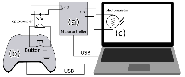
The latency measuring device is based on the broadly available Arduino Micro microcontroller which controls the measuring process, measures the time between input and output and sends results to a PC via USB. An optocoupler is used to close the connection of a button on an input device so an input event triggered. A photo resistor attached to the monitor is used to sense a change in brightness on the display. Additionally, two LEDs indicate the state of the device so it can be validated using a high speed camera.
The measuring device can be seen in Figure 1. The button contacts of the modified input device are connected to the transistor side of an optocoupler (a). The photo resistor is connected to an ADC pin of the microcontroller via a voltage divider circuit (b). Two LEDs indicate the time when a button press is triggered (c, left) and when a change in brightness is detected (c, right). A pyhsical switch (d) can be used to manually start and stop the measurement.
The circuit is kept simple intentionally so it can be replicated easily. Our implementation is soldered to a prototyping board, but the device can also be built on a breadboard so no soldering is required.

Measuring Process
The measuring setup can be seen in Figure 2. A microcontroller (a) starts a timer and triggers a button press on a modified input device (b) by closing a button contact with an optocoupler. The application reacts to the button press by changing its background color from black to white. The microcontroller measures the display's brightness with a photo resistor (c) attached to the monitor. Once a change in brightness is recognized, the timer is stopped. Results sent to the PC via USB.
The measuring process is depicted in Figure 3. (1) The measurement starts. (2) The mouse button is triggered and the green LED is turned on. (3) The input event is recognized by the PC and the screen changes its color from black to white. (4) Once the photo sensor attached to the display measures a change in brightness, the blue LED turns on. This way, the results of our device can be compared to footage from a high speed camera.


Validation
We validated the latency measuring device by comparing its results with annotated footage of a high speed camera (Google Pixel 3a smartphone with 240 fps, Figure 4).
The results of our measuring device match the latencies determined with annotated video footage with a error margin of below 4 milliseconds, which is the high speed camera's temporal resolution. Those measurements were conducted on an HP EliteBook 850 G4 with a Logitech G5 mouse and a Dell U2417h monitor. Results can be seen in Figure 5.
We also measured the internal latencies of all used parts (microcontroller, optocoupler, photo sensor) with an oscilloscope. All measured values were at most in the microsecond range so it is safe to assume that they do not confound the measurements of our device.


Limitations
The biggest limitation of our measuring method is the fact that input devices need to be opened and modified so our measuring device can automatically trigger button presses. We know that this might be a deal-breaker in some scenarios, especially for regular gamers who want to know the latency of their own system. We accept this limitation as - in our experience - electrically triggering button presses is the only replicable method to accurately and automatically trigger input events for button-equipped devices.
One limitation that most methods for measuring end-to-end latency have in common is the fact that even though they can measure latency, they can not give an explanation on partial latencies contributing to the total delay. Therefore, if the goal is to effectively improve a system's latency, more detailed timestamps from the whole processing pipeline have to be collected.
Additionally, our device is only capable of measuring the latency of systems with button-equipped input devices and visual displays. As stated in the beginning, there is no one size fits all solution for measuring latency. However, for many applications, we provide a simple, accurate, and easily replicable method to measure a system's end-to-end latency.
Replicating the Device
The device can either be assembled on a breadboard or soldered to a prototyping board as a more permanent solution. We also plan to provide a PCB layout in the near future.
For our implementation of the device, we used an Arduino Micro, but all comparable microcontrollers with an ADC can be used. The source code for the microcontroller, as well as a test program for the PC can be found on GitHub.
The LED side of an optocoupler has to be connected to the GPIO pins of the microcontroller. To protect the LED, a resistor should be used to decrease the voltage on the optocoupler. The required resistance depends on the microcontroller's operating voltage and the supported voltage of the optocoupler which can be found in the optocoupler's data sheet.
To connect the input device's button to the optocoupler, it is in most cases necessary to open up the device and either solder or clamp wires to the button's contacts (Figure 6). Those wires are then connected to the transistor side of the optocoupler. If the device is assembled on a breadboard, the wires can simply be plugged into breadboard sockets. If a prototyping board is used, we recommend soldering pins or sockets to the optocoupler's transistor side so the wire's can be plugged in and out easily.
A photo resistor has to be connected to an ADC pin of the microcontroller with a wire long enough to be mounted to the top corner of a display. When attaching the sensor to the monitor, we recommend using dark electric tape to shield it from external light. Additionally, this kind of tape can be removed easily and without residuals.
Lastly, we recommend to add a switch to turn the measurement process on and off. The device would theoretically work without the switch, but it would then constantly trigger the input device's button which can be annoying in some situations.

Resources
- Paper: https://osf.io/tkghj
- Source code: https://github.com/PDA-UR/end-to-end-latency
Publications
Florian Bockes, Raphael Wimmer, Andreas Schmid
CHI EA '18 Extended Abstracts of the 2018 CHI Conference on Human Factors in Computing Systems
Development of a tool for measuring latency of different USB devices (Tweet this with link)
![]()
![]()

Raphael Wimmer, Andreas Schmid, Florian Bockes
Proceedings of the 2019 CHI Conference on Human Factors in Computing Systems (CHI '19)
Summary of our current understanding of latency and our approach of measuring the latency of USB-connected devices. (Tweet this with link)
![]()
![]()
Patrick Stadler, Andreas Schmid, Raphael Wimmer
Proceedings of the Conference on Mensch und Computer 2020
Easily replicable device for measuring the reaction time of displays. (Tweet this with link)
![]()
![]()

Andreas Schmid, Raphael Wimmer
Workshop on Esports and High Performance HCI 2021
Measuring device for end-to-end latency based on cheap off-the-shelf components. (Tweet this with link)
![]()
![]()
Andreas Schmid, Raphael Wimmer
Extended Abstracts of the 2023 CHI Conference on Human Factors in Computing Systems
We implemented and evaluated a new method for measuring the latency added by different graphics frameworks and toolkits on X11-based systems. (Tweet this with link)
![]()
![]()
All Related Posts
PDA group at Workshop on Esports and High Performance HCI 2021 (2021-04-10)
Andreas Schmid will present a short paper on a new method for measuring end-to-end latency at the first Workshop on Esports and High Performance HCI, co-located with CHI'21. Further information on can be found on the project page. (more...)
DispLagBox at Mensch und Computer 2020 (2020-09-01)
We will present DispLagBox, a precise and easily replicable device for measuring display latency, as a short paper at Mensch und Computer 2020. (more...)
New paper: On the Latency of USB-Connected Input Devices (2019-05-09)
We presented our paper "On the Latency of USB-Connected Input Devices" at CHI 2019 in Glasgow. (more...)
PDA Group at CHI '2018 (2018-04-21)
We will present a poster and a workshop paper at CHI 2018. (more...)